John Smith Organs

Topsy 3 - Plans

(Late-breaking corrections at the bottom of this page)


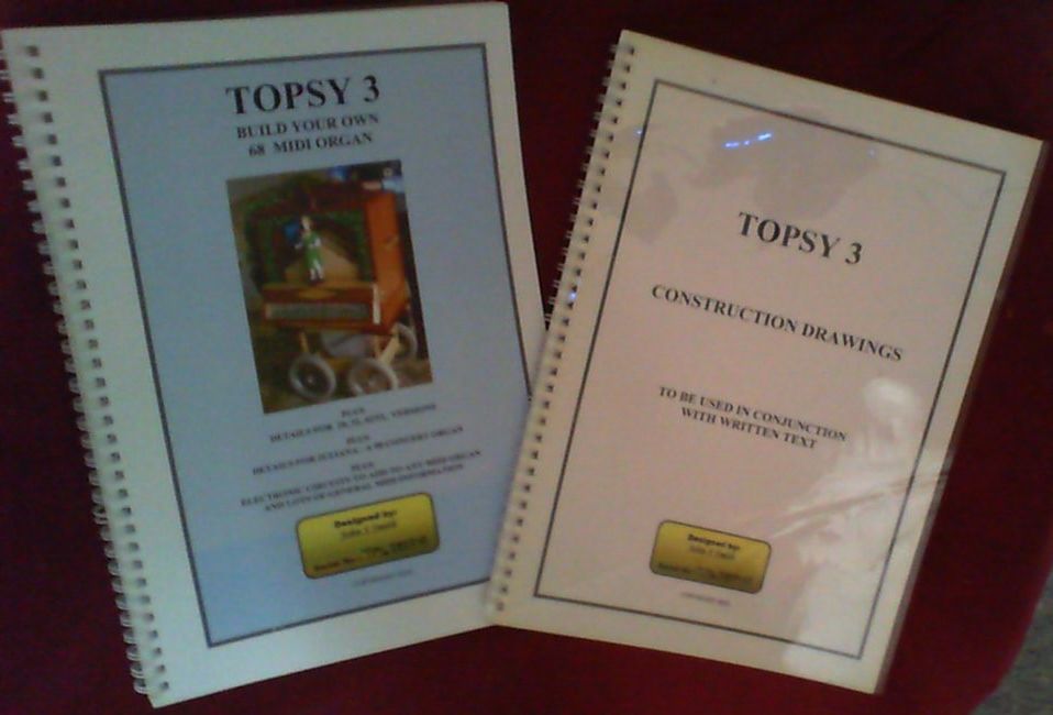
As Topsy 3 represents a major advance in the design of a small portable organ, it is only fitting that the standard of the package supplied for its construction should also be much more sophisticated. As can be seen from the adjacent illustration, the building instructions are supplied in a spiral-bound folder, as are the constructional drawings. Separate folders have been used so that references to drawings, associated text and the DVD can be made at the same time, without having to flip between sections. Everything has been professionally printed, to make both text and illustrations easy to read.

Considerable effort has been expended on making the constructional details as clear, logical and easy-to-follow as possible.  Clicking here will (slowly!) open up a .pdf file showing a sample section of the text (use your browser's Back button to return to this page).   The whole publication is much larger than those in previous packages, so you will see that a contents page has been  included - to ease navigation through the 90 pages of text and drawings.


As shown on the contents page, there is a considerable amount of information provided over and above that needed for making Topsy 3 itself. Details are provided for 20/32/42/52 note versions, and to enable a larger organ to be constructed, with references to John's own 'Juliana' 98 Key MIDI dance organ - which lives in a small converted caravan.

There is also a section entirely devoted to circuits for including Registers to control sections of pipes, with many innovative ideas.  It is worth pointing out that these designs are not specific to Topsy 3, and that they may be suitable for use in any MIDI organ. Each circuit is printed adjacent to its associated text - again to ease the task of cross-referencing.

Buyers of the Topsy 3 Plans will also receive an emailed accessory pack.    This includes sample midi files  from Alan Pell and Melvyn Wright, plus others files for setting up and testing,  as well as music lists.

Topsy 3 plans now include additional information to make a smaller 32 note version.  This still uses most of the Topsy 3 design techniques but cut down to make a smaller, lighter, and cheaper instrument. Using 29 pipes and three percussions, the scale plays Alan Pell 25 to 30 note midi music as well as 20/26 Raffin scale.

It would be fair to say that these plans represent a major step forward from the other much simpler versions for previous organs.

Corrections
With a publication of this size, despite being scanned dozens of times, it is still possible for a few errors to creep in.   As these become known, corrections will be listed here:


Fig 12 on Page 59


    - Full 8 way Register Control, plus Tremulant
As pointed out by Harold M. Whipps Sr, the drivers in the bottom right-hand corner of the diagram were all incorrectly identified as IC4B with pins 2 and 17.
They should be as shown:


# 7, Accompaniment Windchest,  in Construction Drawings


As pointed out by David Seager, the offset for the lower A pipe is shown as 1.25".
It should be 1.75" - to place the pipe in the centre of the available space.

Scales for John Smith Topsy 3, page 25


As pointed out by Bill Klinger, the octave numbers beside each of the A notes should be disregarded completely (my editor got confused!)

MIDI Set-up files


There are a couple of errors in the MIDI set-up files supplied
before August 2010,
so please send an e-mail to request corrected copies - which will also include extra tuning files

Fig 8 on Page 53 - Bellows Motor Speed Control


IC1 is an LM324, not LM342.   The power pins should be:  Pin 4 connected to +12V; pin 11 to 0V.

#13, Counter Melody Pipes


In the table, for note D#, the entry in the Int Depth column should read 1 1/4 not 1 3/16.
Also, for note E, the Int Depth and Int Width figures should both be  1 3/16


#14, Melody Octave Pipes

The dimension in the 'ALL PIPE WALLS . . . . ' note should be 3/32" not 3/36"

# 8, Melody Bourdons


The lower F# pipe is missing from the table, but as shown in the cutting list, its dimensions are the same as the F pipe.  On the other hand, the top G pipe is included in the table, but is NOT needed - it is the MIDI note used for the Snare Drum


# 6, Accompaniment Pipes


The width and depth on the Full Size A# pipe drawing do not match the dimensions given in the table, so use the table dimensions for cutting - not forgetting to add 2 x wall thickness to internal depth dimension

Fig 8 on Page 53 - Bellows Motor Speed Control (added 18/10/2011

)
The 0.1uF capacitor and 100k resistor shown connected to pin 10 on IC1C should be connected instead to pin 9.
Also, the 10uF capacitor connected to pin 5 of IC1B should be replaced with a 0.1uF capacitor, and the 10uF capacitor re-connected between +12V and 0V.
Later Change  -   added 20-08-12
The 100K resistor  and 0.1uF capacitor should be removed.   A 47k resistor (or a 120k pre-set) should be inserted between the pole of switch S2 and pin 9 of  IC1C.    A 4.7uF capacitor should also be connected to pin 9  and 0V.  This change slows down the otherwise abrupt change-over between the motor being in normal running and idling modes.


Fig 1 on Page 46 - Powers Supply Protectionl (added 03/09/2013)
Fig 2 on Page 47 - Basic Solenoid/Decoder Wiring(added 03/09/2013)


A diode should be added across the terminals of the relay coil.